There are several other components in the fuel indicating system which could be the issue or are causing the indication problems:
- Ensure that your aircraft fuel indicating system utilized Stewart Warner style transmitters.
- Even if your aircraft originally came with that style, there were many Cessna Service Bulletins to replace them with the Rochester style. Our transmitters will not work with those components if they have been changed. This was a very common SB when Cessna switched over to Rochester.
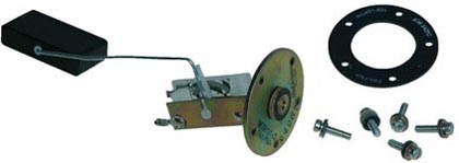
- Transmitter Identification shows the difference in the Rochester style and the original Stewert Warner transmitter.
- McFarlane transmitters and Cessna Stewart Warner transmitters have an electrical resistance range of about 32 ohms when in the full position and 250 ohms in the empty position. This can be measured with an ohm meter connected between the wire terminal and the metal body. Note that the gold dichromate corrosion treatment on the zinc plating is a poor conductor. The metal body must be scratched a little to get a good electrical connection. The Rochester transmitter has a much different resistance pattern than the Stewart Warner or McFarlane transmitter.
- Consult your log books and check the part numbers of the fuel gauges and transmitters. Do not rely on Illustrated Parts Catalog or eligibility.
- With the age of most of the general aviation fleet, the possibility of corrosion in the wires or grounding is very likely. The gauge (indicator) may not be working correctly or properly calibrated.
- Since the transmitter gauge system works with very low voltage and very low milliamp electrical flow it is very sensitive to proper grounding and high resistance in electrical connections. Most problems are related to electrical connections.
- Excess resistance in the transmitter circuit can be detected by measuring the transmitter resistance with the transmitter being installed but without the wire connected at the terminal, and then measuring the resistance at the transmitter wire at the back of the gauge with the transmitter wire connected to the transmitter terminal and the transmitter wire disconnected from the fuel gauge and the other ohm meter connection to a ground at the back of the gauge. The resistance readings should be very close to the first resistance reading. In other words, you are measuring the transmitter resistance first without the airplane circuit and then comparing the reading with the airplane electrical circuit.
- If the preceding wiring check shows good, the problem is likely in the gauge. The fuel gauge has a brass grounding strap that grounds the internal electrical coils to the gauge case. With years of service this grounding strap can develop a thin layer of corrosion that restricts electrical flow. When this happens the gauge will show more fuel than what is in the tank which is not good! Cleaning this ground strap should fix the problem. Refer to the Cessna service manuals for detailed trouble shooting and maintenance information.
Caution! Never short the battery power to the transmitter wire! It will take only seconds before the stainless steel resistance wire in the Cessna transmitter will glow red hot in the fuel tank. The hot wire could explode the tank! Never have power on when trouble shooting the fuel gauging system.
Electricity in the Fuel Tank. Is it Safe?
Always check the fuel gauge system for proper calibration per the Cessna maintenance instructions.